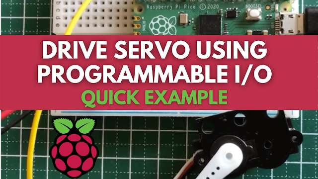
Raspberry Pi Pico: This is an example project for driving a servo with a Programmable I/O.
PIO (Programmable I/O) is a new piece of hardware designed specifically for the RP2040 Microcontroller. It enables the creation of new (or extra) hardware interfaces on an RP2040-based device. Although the RP2040 has dedicated hardware PWM, we will utilise PIO to drive a servo motor in this tiny project.
 |
| Wiring Diagram |
#include "hardware/clocks.h"
#include "hardware/pio.h"
#include "pico/stdlib.h"
#include "pico_servo.pio.h"

#define MIN_DC 650
#define MAX_DC 2250
const uint SERVO_PIN = 16;

/* Write `period` to the input shift register */
void pio_pwm_set_period(PIO pio, uint sm, uint32_t period) {
    pio_sm_set_enabled(pio, sm, false);
    pio_sm_put_blocking(pio, sm, period);
    pio_sm_exec(pio, sm, pio_encode_pull(false, false));
    pio_sm_exec(pio, sm, pio_encode_out(pio_isr, 32));
    pio_sm_set_enabled(pio, sm, true);
}

/* Write `level` to TX FIFO. State machine will copy this into X */
void pio_pwm_set_level(PIO pio, uint sm, uint32_t level) {
    pio_sm_put_blocking(pio, sm, level);
}

int main() {
    PIO pio = pio0;
    int sm = 0;
    uint offset = pio_add_program(pio, &pico_servo_pio_program);

    float freq = 50.0f; /* servo except 50Hz */
    uint clk_div = 64;  /* make the clock slower */

    pico_servo_pio_program_init(pio, sm, offset, clk_div, SERVO_PIN);

    uint cycles = clock_get_hz(clk_sys) / (freq * clk_div);
    uint32_t period = (cycles -3) / 3;
    pio_pwm_set_period(pio, sm, period);

    uint level;
    int ms = (MAX_DC - MIN_DC) / 2;
    bool clockwise = false;

  while (true) {
    level = (ms / 20000.f) * period;
    pio_pwm_set_level(pio, sm, level);

    if (ms <= MIN_DC || ms >= MAX_DC) {
        clockwise = !clockwise;
    }

    if (clockwise) {
        ms -= 100;
    } else {
        ms += 100;
    }

    sleep_ms(500);
  }
}
The following software generates PWM signals on a GPIO pin.
; Side-set pin 0 is used for PWM output
.program pico_servo_pio
.side_set 1 opt
  pull noblock  side 0 ; Pull from FIFO to OSR if available, else copy X to OSR.
  mov x, osr        ; Copy most-recently-pulled value back to scratch X
  mov y, isr        ; ISR contains PWM period. Y used as counter.
countloop:
  jmp x!=y noset  ; Set pin high if X == Y, keep the two paths length matched
  jmp skip  side 1
noset:
  nop  ; Single dummy cycle to keep the two paths the same length
skip:
  jmp y-- countloop ; Loop until Y hits 0, then pull a fresh PWM value from FIFO

% c-sdk {
  static inline void pico_servo_pio_program_init(PIO pio, uint sm, uint offse t, uint clk_div, uint pin) {
  pio_gpio_init(pio, pin);
  pio_sm_set_consecutive_pindirs(pio, sm, pin, 1, true);
  pio_sm_config c = pico_servo_pio_program_get_default_config(offset);
  sm_config_set_sideset_pins(&c, pin);
  sm_config_set_clkdiv(&c, clk_div);
  pio_sm_init(pio, sm, offset, &c);
}
%}#define MIN_DC 650
#define MAX_DC 2250Create the code
$ export PICO_SDK_PATH=/path/to/pico/pico-sdk
$ git clone https://github.com/metanav/pico_servo_pio.git
$ cd pico_servo_pio
$ mkdir build && cd build
$ cmake ..
$ make
Following the procedures below, we may upload the produced pico pio pwm.uf2 binary file to the Raspberry Pi Pico.
- Connect the Raspberry Pi Pico to your computer's USB port while pressing and holding the BOOTSEL button. It will appear as RPI-RP2, a Mass Storage Device.
- Drag the pico pio pwm.uf2 binary to the RPI-RP2 volume and dump it there.
The Raspberry Pi Pico will reboot after flashing the binary, and the software will begin to execute.
GitHub: Drive servo with Raspberry Pi Pico using PIO
Posts You May like:
- How to Use a USB SSD or Flash Drive to Boot a Raspberry Pi 4 / Pi 400
- Filter Ads by your Raspberry Pi Before they Reach your Devices
- A Raspberry Pi 4 Model A Launch 2022 - Eben Upton
- First-Ever 2G Expansion Board for Raspberry Pi Pico has Launched on Kickstarter
- Learn IoT "Internet of Things" with 24 lessons for Teachers and Students
- Quick Guide for Raspberry Pi Users: Raspberry Pi Terminal Commands
- Windows 11 on Raspberry Pi Devices in Easy Installation Guide
- Get Your Project Done by Raspberry Pi Approved Design Partners
- PiRelay 8 Smart Relay Board for Raspberry Pi - Kickstarter
- Tiny Round/Circular LCD Display Launched!
- Issue Fixed! USB Boot Ubuntu Server 20.04 on Raspberry Pi 4
- HC-SR04 Sensor with micro-ROS on the Raspberry Pi Pico
- Raspberry Pi Pico: ADC Sampling and FFT
- Using CircuitPython for RP2040
- How to Setup Pico RP2040 on Windows
- Using micro-ROS on the Raspberry Pi Pico
- LED Tricks Using The Raspberry Pi Pico
- The RP2040 Raspberry Pi Pico Meets LoRa
- Pico supports SD cards and FatFS
- How to connect a Raspberry Pi Pico to LoRaWAN
- 50 Raspberry Pi Hacks & Tips You Should Know
- How to Install Wi-Fi and Internet on a Raspberry Pi Pico


